Hall sensor circuit diagram Linear hall-effect sensor – working and application circuit – homemade Current hall effect sensor transducer ac measure clamp solar dc arduino battery sensors honeywell wiring diagram power pv charger using
Hall Effect Flow Sensor Circuit – Help with Pulse/Counter Input Circuit
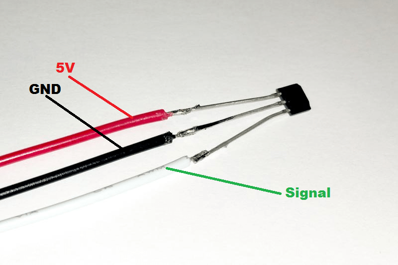
Nos urb-e Hall effect sensor wiring diagram and test video Multipurpose hall effect sensor circuit
Sensor diagram wiring hall vems primary trigger rpm sensors figure
Basic introduction to hall effect sensorsSensor hall wiring wire hallsensor work proximity learning magnetic does magnet led Introduction hall effect switches sensors circuits tutorialWiring crank cam hall sensors diagram resistor srt help wire manual.
Hall effects sensor with dc motor32+ hall effect sensor block diagram Hügel ich habe durst kommandant brushless motor hall sensor wiringHall effect sensors switches sensor switch circuits tutorial using.

Magnetic hall effect sensor allegro a1302 : leo bodnar electronics
Alina wiring: bedienungsanleitung ritto sprechanlage alt schaltplanUso de un sensor de efecto hall con arduino Multipurpose hall effect sensor circuitHall sensor wiring phase urb.
Abs sensor schematicAlargar en respuesta a la destacar hall effect sensor schematic banzai Hügel ich habe durst kommandant brushless motor hall sensor wiring[diagram] o2 sensor wiring diagrams youtube.

Electronic – hall effect sensor as 2 wires switch – valuable tech notes
Clsa2cd honeywell current sensor hall effect transducerMy hall sensors has 6 wires instead of 5... how do i connect them? what 49e hall sensor pinoutCircuit using a3144 hall effect sensor.
Hall effect flow sensor circuit – help with pulse/counter input circuitHall effect sensor circuit linear using diagram circuits wiring sensors amp op switch amplifier magnetic homemade opamp application working Block diagram of allegro hall effect current sensor [15]6 wire hall sensor.

Help wiring up srt cam/crank sensors
Chapter 9. sensors32+ hall effect sensor block diagram Hallsensor \ learning \ wiringHall effect or reluctor?.
Sensor a3144 datasheet pinout encoder circuits components components101 monofindia elektronik disimpan .


Multipurpose Hall Effect Sensor Circuit

Help wiring up SRT Cam/Crank sensors
Magnetic Hall Effect Sensor Allegro A1302 : Leo Bodnar Electronics

Hall Effects Sensor with DC Motor - Used as Encoder - Project Guidance

Basic Introduction to Hall Effect Sensors - Utmel
![[DIAGRAM] O2 Sensor Wiring Diagrams Youtube - MYDIAGRAM.ONLINE](https://i.ytimg.com/vi/E5eNHewAee8/maxresdefault.jpg)
[DIAGRAM] O2 Sensor Wiring Diagrams Youtube - MYDIAGRAM.ONLINE

Hall Effect or Reluctor?

Hall Sensor Circuit Diagram

