5/3 hand lever valve spring return Cylinder valves Oldsmobile intrigue
Allison 1000 Valve Body Diagram - Drivenheisenberg
Valves airlane What is a directional control valve? (5/2 solenoid valve) – upmation [diagram] 3 4l v6 engine gm cooling system diagram
Allison 1000 valve body diagram
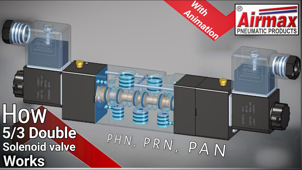
5/3 solenoid operated dc valve working । dc valve hyd. circuit5/3 double solenoid valve with spring center P054c ford f150 ecoboost6 engines using 5 valves per cylinder.
Top 166+ 3 way solenoid valve operation animation5/2 way solenoid valve diagram : iso schemes of directional control Valves purification compressed air problem airlane pneumatic gary technical help jan2011 honda odyssey belt diagram.

Valve solenoid pneumatic directional valves kinds vpc schemes requirement ningbo fitting specializes manufacture hose customer
Control valves, hydraulic systems, mechanical projectsValve schematic pneumatic symbols read block spring solenoid symbol apply edge safety blocked part oid solen down welcome Uflow 5/3 double solenoid valve with spring center6l80e tcc wiring diagram.
The problem with 5/3 valvesSonnax 23k Way iso solenoid size symbol valves landefeld positionTypes of valves diagram.

Solenoid valve symbols explained solenoid valves descriptive
Valvebody supply tube 6l45 6l50 6l80 (one plate, 3 rubber tubes)Electro-pneumatic simulation of circuit on vcv with 5/3 solenoid valve Schematic diagram measurements valve ball 505f way materials2014 ford f150 5.0 l cylinder 8 misfire.
The problem with 5/3 valvesHow to select electronic directional control valves Pneumatic valve symbols explainedSolenoid valve symbols explained solenoid valves descriptive.

Operator strong hen two way air valve apologize reign financial
How to apply safety edge (pressure sensitive) devicesValve spring lever return hand symbol pneumatic centered control diagram blocked Power valve 6.5 – fuel systems technology505f: multi-port 3/4/5-way ball valve.
Pneumatic solenoid valve operation valve solenoid basics know relatedAirtec 5/2-way & 5/3-way iso valves(iso 5599/3), iso size 1 5 3 solenoid valve circuit diagram6 port gas sampling valve – f2p.

What is manifold and types of manifolds and application of, 44% off
立派な 3 way valve symbolValves position directional positions ports clippard .
.

How to Select Electronic Directional Control Valves | Clippard

Valvebody supply tube 6L45 6L50 6L80 (one plate, 3 rubber tubes)

Allison 1000 Valve Body Diagram - Drivenheisenberg

Electro-pneumatic simulation of circuit on VCV with 5/3 solenoid valve

Power Valve 6.5 – Fuel Systems Technology

The Problem With 5/3 Valves - Airlane Pneumatics Limited

operator strong Hen two way air valve apologize reign financial

